Machine type | H6x10 | H9x14 | H12x18.5 | H15x20 | H20x20 | H25x35 |
| H30x40 | H35x35 | H40x50 |
|
Max. working Ø [mm] | 600 | 900 | 1200 | 1500 | 2000 | 2000 |
| 2000 | 2000 | 4000 |
|
Max. working height [mm] | 1000 | 1400 | 1850 | 2000 | 2200 | 2500 |
| 3000 | 3000 | 5000 |
|
Hook type | M. | M / A | M / A | M / A | A. | A. |
| A. | A. | A. |
|
Max. hook load [kg] | 2x350 | 2x500 | 2x500 | 2x500 | 2x1,000 | 1x2,000 |
| 1x5,000 | 1x10,000 | 1x10,000 |
|
Power of the turbine [ kW ] | 2x4 | 2x5.5 | 2x7.5 | 3x7.5 | 3x11 | 5x7.5 |
| 5x11 | 5x18.5 | 7x18.5 |
|
Magnetic separator | Yes | * | * | * | * | * |
| * | * | * |
|
|
|
|
|
|
|
|
|
|
|
|
|
M ... manuel / A ... automatic / * optional |
|
|
|
|
|
|
|
|
|
|
|
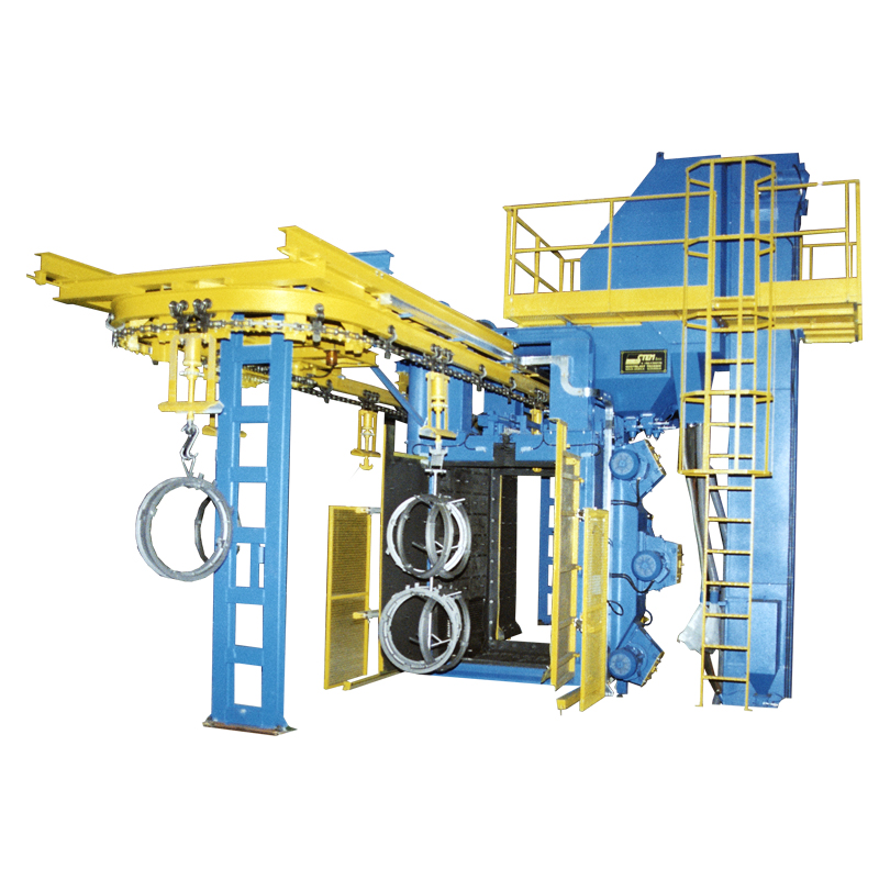
Overhead conveyor - type "O"
Blast wheel systems of this type are called in the German O-Hängebahn track or in the English "CH" (Chain Hook), because the workpieces to be blasted are suspended, grapevine-like or individually hung on the so-called hangers. These hangers are attached to rotating hooks that can be transported along a chain hoist. A rotation within the machine exposes the entire surface of the work piece to the continuous <s>jet</s> blast of the centrifugal wheels. The work cycle is as follows:
• Workpieces are loaded onto the hangers outside the machine. Loading can be done manually or by means of an electric chain hoist mounted on the carriage.
• The hangers loaded with workpieces are then transported to the blasting position in the blasting chamber by means of a fully automatic electric overhead conveyor.
• As soon as the workpieces have reached the blasting position, the door must be closed (manually or automatically) so that the blasting room is protected against dust. As soon as the <s>jet</s> blast turbine starts, the door is locked.
• From this point the automatic blasting process begins. During the blasting cycle, the hanger rotates continuously and is automatically transported to a second preset blasting position. This is necessary in order to optimally blast all component surfaces of the suspended workpieces.
• The amount of blasting media is set and controlled by an electro-pneumatic regulated valve. From there it arrives at the center of the centrifugal wheel, from where it is fed through the distributor to the centrifugal wheel blades. The rotation of these blades spins the abrasive onto the components to be cleaned or deburred.
• The mixture of blasting media, burrs, sand deposits, tinder and/or other impurities ends up in the lower part of the machine (system hopper). From there it is transported to the bucket elevator by longitudinal and transverse screw conveyors or a vibrating screen. (The vibrating screen separates the abrasive from larger impurities)
• From here the mixture is transported up to the abrasive preparation (air sifting). (If steel blasting media have to be separated from cast sand, a special magnetic separator is also used). The air separation separates dust and impurities from the clean and reusable blasting media.
• The waste is conveyed into a downpipe, which discharges the impurities from the closed circuit. The clean blasting media is continuously refed into the silos. From there it is returned to the blasting wheels via the control valve, which closes the blasting media cycle.
• The extraction of dust from the blasting chamber and from the abrasive preparation is carried out by a central exhaust air and filter system.
• As soon as the work cycle is finished, the door opens (with manual doors a visual and acoustic signal sounds that the door can be opened) and the hanger is automatically transported to the entrance of the steel chamber. From there, the hanger must be transported to the unloading position (manually or automatically depending on the type of conveyor belt)

OPTIONS |
Frequency control of blast wheels
|
Ablation | Paint stripping | Rust removal |
Descaling | Roughening | Solidifying / |
Desanding | Smoothening | Finishing |