Machine type | T7.5 | T11 | T14 | T18 | T23 | T42 | T50 |
Table Ø [mm] | 750 | 1100 | 1400 | 1800 | 2300 | 4200 | 5000 |
Working height [mm] | 400 | 450 | 670 | 900 | 900 | 2500 | 3000 |
Load capacity of the table [kg] | 400 | 600 | 600 | 700 | 1,500 | 30,000 | 80,000 |
Power of the turbine [ kW ] | 4th | 5.5 | 5.5 | 2x7.5 | 2x7.5 | 4x22 | 6x22 |
Magnetic separator | X | X | X | ** | ** | ** | ** |
|
|
|
|
|
|
|
|
* Table with 2 satellites |
|
|
|
|
|
|
|
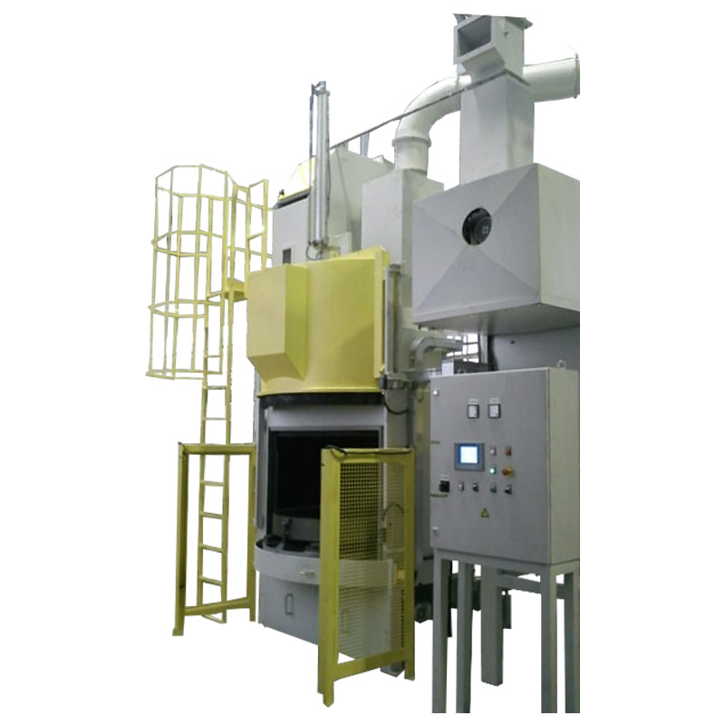
Turntable - centrifugal wheel - type "T"
Blast wheel systems with a turntable are called "T" (table) because the workpieces to be blasted are placed on a turntable. This table is driven in the blasting room and the workpieces are moved continuously through the blast of the centrifugal wheels.
The working cycle is as follows:
• Workpieces are placed on the turntable. Loading can be done manually or using auxiliary tools.
• As soon as the door has been closed (manually or automatically), the dust-tight protection of the blasting room is guaranteed. When the blast turbine starts, the door is locked.
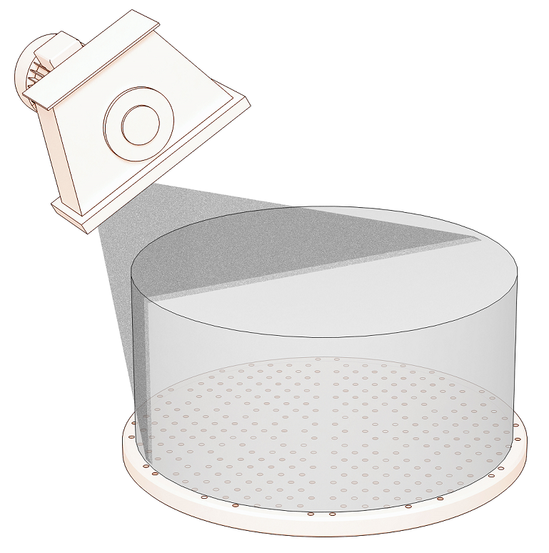
• From this point the automatic blasting process begins. During the blasting cycle the turntable rotates continuously and the component surfaces of the workpieces placed on the table are moved past the blast of the centrifugal wheel and thus optimally blasted.
• The amount of blasting media is set and controlled by an electro-pneumatic regulated valve. From there it arrives at the center of the centrifugal wheel, from where it is fed through the distributor to the centrifugal wheel blades. The rotation of these blades spins the blasting media onto the components to be cleaned or deburred.
• There are holes in the turntable that allow the mixture of blasting media, burrs, sand deposits, tinder and/or other impurities to drain into the lower part of the machine (system funnel). From there it is transported to the bucket elevator by a screw conveyor.
• From here the mixture is transported up to the blasting agent preparation (air sifting). (If steel blasting media have to be separated from cast sand, a special magnetic separator is also used) The air separation separates dust and impurities from the clean and reusable blasting media.
• The waste is conveyed into a downpipe, which discharges the impurities from the closed circuit. The clean blasting media is continuously fed into the silos. From there it is returned to the blasting wheels via the control valve, which closes the blasting media cycle.
• The extraction of dust from the blasting chamber and from the abrasive preparation is carried out by a central exhaust air and filter system.
• As soon as the work cycle is finished, the blasted components can be removed or turned after opening the manual door.
| Frequency control of the centrifugal wheels Centrifugal wheels made of Carbide Protective device in the blasting chamber of carbide instead of manganese steel |
Ablation | Paint stripping | Rust removal |
Finishing | Smoothing | Matting |
Structuring | Refining |
|